Now that we have our Mesh, and we've moved it to the GPU, we have to actually render it
using the GPU. Shaders are programs stored on the GPU that can be run in parallel for large
sets of data. This is what makes the GPU so efficient for rendering items on the screen. We could have
thousands of vertices on the screen at a any given time. If we were to render each of these vertices
one at it time, it would take forever to render even a single frame, let alone 60 frames each second.
The GPU, however, has potentially thousands of cores that can all run in parallel. However, while it has a
lot of cores, each of the cores is significantly smaller than a typical CPU core. As a result, programs
run on the GPU are limited in size, and should primarily be used for performin mathmatical operations with as
few branches as possible.
There are six stages to the render pipeline that all run in a linear sequence:
Vertex Shader -> Shape Assembly -> Geometry Shader ->
Tests and Blending -> Fragment Shader -> Rasterization
For most graphics programmers, we only really care about the Vertex Shader and the Fragment Shader
stages of the pipeline, everything else is done automatically for us (though occasionally we may modify
the geometry shader, but I won't be going over that).
Before we get into the specifics of the Vertex and Fragment Shader, lets go over a few general concepts
in he shader world: input, output, and uniforms.
Inputs and Outputs:
Every stage of the shader process has a series of inputs and outputs. These inputs are the outputs created
after the previous stage of the render pipeline completed. In general, you can think of the render pipeline
as being a conveyer with a bunch of machines that moves the data along from one machine to another.
Each of these machines takes in the data and transform it, until at the very end you have an image that
can be drawn to the screen. So, the input of one machine is the output of another.
Uniforms:
When writing shaders, there is often some data that will be the same for every vertex in a mesh.
These are called uniforms. Uniforms can be used for all sorts of things. For example, you may want to
color your whole object a single color. Rather than store a color value on every vertex, you can store one
uniform color, and use that on each vertex in the shader. Uniforms are used all over the place, because
often an object, while made up of many vertices, has object-wide properties that we don't want to store
in every vertex.
Vertex Shader
The Vertex Shader is the first stage of the render pipeline and run over every vertex in your mesh.
Since the vertex shader is the first stage of the pipeline it's input is provided from the CPU in the
form of a vertex buffer. The primary output of the vertex shader is the screen-view position of the
vertex (the normalized (x,y,z) position in relation to the OpenGL window also known as normalized
device coordinates).
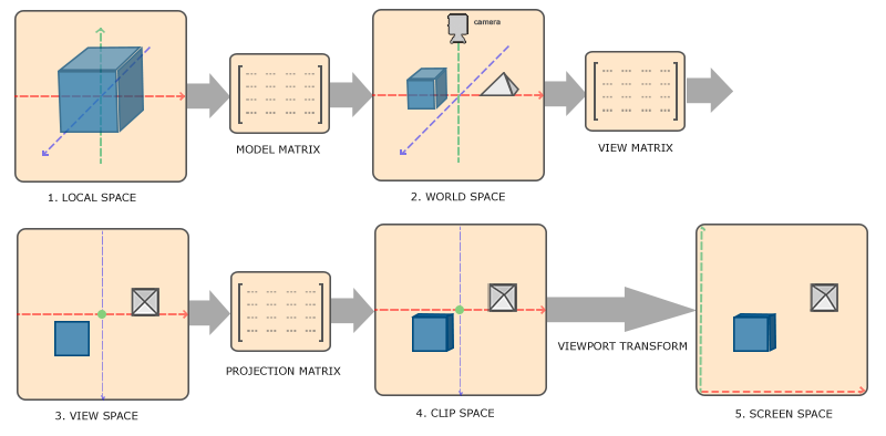
To achieve this output, we use the the matrix transformations above. However, all of these Matrices are
used for transformations are kept on the CPU. This is where Uniforms come in handy. Before running the vertex
shader, I make sure to create a Uniform for each of the matrices (model, view, and projection). Then, I simply
multiply the vertex position by the matrices in the proper order.
Here's the Vertex Shader used for rendering a mesh written in GLSL 3:
    #version 330 core
    layout (location = 0) in vec3 pos;  //Vertex Position Input
    layout (location = 1) in vec2 uv0;  //Vertex Texture Position Attribute


    out vec2 texCoord;                  //Output Texture Coordinate to fragment shader

    uniform mat4 model;                 //The mesh model Matrix
    uniform mat4 view;                  //The scene view matrix
    uniform mat4 projection;            //The scene projection matrix


    void main()
    {
        //Set the texure Texture Coordinate output
        texCoord = vec2(uv0.x, uv0.y);

        //Set the default gl_position output
        gl_Position = projection * view * model  * vec4(pos, 1.0f);
    }
As you can see, the shader looks a lot like a simple C program. The key difference is the variables declared at
the top are inputs and outputs. The 'pos' and 'uv0' are the vertex attribute input given. Inputs are defined
using the 'in' keyword. The 'layout' keyword is used to tell the shader at what position in the vertex the input is
located at. After the input comes the use defined output, which in this case is the texture coordinate (the 2D position
in the texture that the vertex should display). There are also a few default ouputs, like gl_position is a that don't
have to be declared. Finally, the Uniforms are declared, which in this case are the 3 transformation matrices we will
be using to get the screen position of the vertex (gl_position).
After finishing in the Vertex Shader, the outputs are passed into the fragment shader.
Fragment Shader
The Fragment shader is one of the last stages of the render pipeline. The fragment shader is run for every fragment on the
OpenGL window. For simplicity, you can think of these fragments as being the individual pixels on the screen (though sometimes
they are different sizes). The primary output of the fragment shader is the color that the current fragment should be rendered
as using an RGBA (red,green,blue,alpha) color encoding. We represent this color as a 4D Vector, where each position is a value
between 0 and 1.
Here's the Fragment shader associated with the Vertex Shader above:
    #version 330 core

    in vec2 texCoord;               //The texture coordinate given to use by the vertex shader

    out vec4 FragColor;             //The output color that the fragment will be drawn with

    uniform vec4 ourColor;          //A Uniform that we use to modify the color of the entire object
    uniform sampler2D ourTexture;   //The texture to draw on the surface of the object

    void main()
    {
        //Set the color output to the texture color multiplied by object color
        FragColor = texture(ourTexture, texCoord) * ourColor;
    }
This time, you'll notice I didn't define my inputs using a location. Instead, I just have to make sure my input
name matches the output name of the vertex shader. The compiler will automatically assign the outputs of the
vertex shader to the inputs of the fragment shader. I have only 1 output in the fragment shader, and thats the
fragment Color I want to draw to the screen.
Using these 2 Shader's, we can create a Shader Program and compile it on the GPU. Once we do this, OpenGL
give's us a Shader ID, which we can use to tell the GPU which shader program we want to use when rendering our objects.